Leading the world in
energy absorption
With increasing accidents of elevators free falling, it has become necessary to pay attention to impact energy absorption solutions, as those provided by Oleo.
Oleo is a leading expert in (impact) energy absorption technology, designing and manufacturing energy absorption solutions for the elevator, rail and industrial sectors. With an ongoing investment in research and development, the Company is continually updating designs and introducing new products and services.
Oleo elevator buffers are designed to protect people and equipment from forces generated either during normal running, or from an impact resulting from equipment failure or operator error. Oleo has achieved this by using hydraulic energy absorption systems combined with a gas return spring to give unsurpassed energy dissipation and recovery.
Elevator buffers are safety devices which are required to be mounted at the base of an elevator shaft. As with any safety device, elevator buffers have to meet with a variety of specifications. But, probably, the most important of these is the manner in which the buffers must bring an impacting elevator car to rest. There are different technical specifications for elevator buffers in different regions worldwide. However, all employ the same basic performance criteria.
There is a fear of being a passenger inside an elevator freefalling into the basement of a high rise building although this is practically an impossible event. Since the very early days of elevators, a variety of safety systems have been employed to ensure that the elevator will not free fall.
The purpose of elevator buffers is to provide protection against the malfunction of an elevator control system resulting in the elevator continuing to travel past the lowest stop to the base of the elevator shaft. The buffers are specified in accordance with the operating velocity and mass of the elevator.
Although freefall is not a realistic event for an elevator, it is used in the specification of the buffer performance.
The requirement for elevator buffers falls into two categories depending on the type of buffer.
Energy accumulation buffers: These can take the form of simple mechanical springs or polymer buffers. They store the absorbed energy of the impact in the form of strain energy. In some accumulation buffers, this stored energy can be dissipated on the return movement of the buffer leading to two separate requirements.
a) Buffers with linear and non linear characteristics. These can be used if the elevator does not exceed 1.0m/s
b) Buffers with buffered return movement. These can be used for elevators that do not exceed 1.6m/s.
Energy dissipation buffers: These are usually hydraulic buffers which dissipate the energy of the impact in the form of heat during the travel of the buffer. This type of buffer can be used for all rated speeds, but must be used for speeds of 1.6m/s or over.
Performance criteria in all specifications is governed by two underlying rules, which state that the buffer must arrest a freefalling mass travelling at 115 percent of the rated speed of the elevator:
(i) With an average deceleration not exceeding 1g.
(ii) Without exceeding a deceleration of 2.5g for a time period greater than 0.04 seconds.
In addition, a further but separate requirement states that the buffer stroke must be at least as great as freefall distance required to reach 115 percent of the rated elevator velocity. It is this requirement that dictates the stroke and, consequently, the installation height of elevator buffers. Due to customer demands, most elevator buffers do not deviate far from the minimum stroke requirement.
Minimum buffer strokes for specific rated speeds:
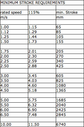
The design engineer must consider the stroke requirements in the overall height of the buffer. If telescopic solutions are not to be used, then the overall height must be at least double the minimum stroke with a further height requirement to restrict lateral movement when the buffer is fully extended. Lateral movement should be restricted to +/- 5mm/metre of stroke from the centre.
The function of an emergency terminal speed limiting device is to automatically reduce the speed of a car or counterweight by removing power from the driving machine. The device effectively slows the car or counterweight to the rated speed of the buffer before impact. This device would normally be independent of the normal terminal slowdown devices.
This is important when selecting a buffer for a particular application. If the emergency terminal speed limiting device is part of the installation, then the ‘reduced stroke’ rules can apply. This effectively reduces the size of buffer required for a particular application.
The calculation for reduced stroke is based on the stroke of the buffer and not the speed of the elevator. The reduced stoke calculation differs in some countries, but the basic rules are as follows:
The stroke must not be less than:
a) One half (50 percent) of the stroke for elevators that do not exceed 4.0m/s.
b) One third (33.3 percent) of the stroke for elevators where the speed exceeds 4.0m/s.
Minimum strokes also apply under some code requirements including EN81. Under EN81, the minimum stroke should be 420mm for 50 percent calculation and 540mm for the 33.3 percent calculation. This does not apply under all code requirements.
Using the reduced stroke calculation, a buffer rated at 5.09m/s (1002ft/min) could be used on an installation of 8.8m/s if used with a terminal speed limiting device.
At first glance, it might seem implicit that if the buffer’s stroke (i.e. the stopping distance) is equal to – or greater than – the freefall distance then the average ‘g’ requirement will be fulfilled. This is only true if the deceleration imparted by the buffer is uniform. Uniform deceleration is not a requirement. In fact, the buffer may bring the mass to rest in any manner as long as the rules above are upheld.
Elevator buffers are designed to be used on a range of different elevators; the mass of elevators vary as do the potential load conditions. Meeting the buffer performance criteria for a given elevator mass is relatively straight-forward, but meeting the same criteria over a range of masses is significantly more difficult. If the lighter elevators are exposed to the same forces as the heavier elevators, they will be exposed to greater decelerations. A 125kN force acting on a 5-tonne elevator will result in a deceleration of 2.5g. The same force acting on a 1-tonne elevator will result in a deceleration of 12.5g. The wider the mass range, the greater the challenge for the buffer designers.
By precise control of hydraulic damping, Oleo's elevator buffers can have a mass range as wide as 12:1. Building a wide mass range buffer can be accomplished by controlling the deceleration of masses throughout the buffers stroke.
Staying within the allowed performance criteria by utilising the fact that an average deceleration of 1g can be maintained by simply extending the time it takes the buffer to fully stroke. In this regard, the limiting part of the performance criteria becomes the requirement not to exceed a deceleration of 2.5g for a time period greater than 0.04 seconds.
The specifications governing elevator buffers state only the maximum duration that the decelerations can be above 2.5g; they place no restriction on the magnitude of the deceleration itself. It is interesting to note that if an elevator was to decelerate at 2.5g for 0.04seconds, it would result in a change in velocity of 1m/s. This means that elevators travelling less than 1m/s cannot fail this criterion.
The lack of an upper limit to deceleration means that it is possible to design buffers that exert very high decelerations on elevators within the 0.04second duration. An elevator decelerating an average of 6.25g for 0.04sec would result in a change in velocity of 2.5m/s – the vast majority of elevators operate below 2.5m/s.
The approach Oleo adopts when designing an elevator buffer is to achieve a similar maximum deceleration across the mass range. For example, a peak transient deceleration of 4g may be achieved on an impacting elevator regardless of whether this is at the bottom, top or middle of the buffer's mass range. It is by using this approach that Oleo believes that its wide mass range elevator buffers not only have economic benefits but are also a safer option.
Oleo elevator buffers are designed to withstand many more maximum load impacts than elevators are likely to experience in their service life. Despite this, elevator buffers remain an emergency only device. It is never a desirable outcome in the real world to have to rely on buffers to bring your elevator to a stop - that said, it is absolutely essential that you can rely on the buffers in the event that they are required.
It is for this reason that many elevator buffers are fitted with a switch. The switch is positioned to detect that the buffer is fully extended and, therefore, ready for impact in the case of an emergency. If for any reason the switch does not detect full buffer extension, the entire elevator system is shut down.
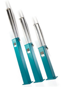
Oleo elevator buffers
Oleo employs computer modelling and analysis to refine elevator buffers performance. Simulations are compared directly with test results obtained on Oleo's own in-house dynamic test facility. The ability to both simulate and test has allowed increased optimisation of elevator buffer performance, providing benefits in terms of cost, safety and reliability.
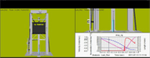
Oleo provide elevator impact simulation to validate test results.
Elevator buffers are subjected to a type test before they can be sold to the market. Type test requirements vary depending on country but most follow the guidelines of the European specification EN81.
To comply with the requirements of EN81, the buffer must perform to the criteria detailed earlier in this article. To establish this, the buffers are subject to drop tests. This is where a mass is dropped in freefall. The drop tests must take place at a temperature between 15° and 25°C.
Tests are conducted with masses at either extreme of the stated mass range of the buffer. Subsequent to the maximum mass drop, the mass must remain on the buffer for a minimum of five minutes, after which the buffer must fully re-extend within a time period of 90 seconds. Measurements must be made of the displacement, velocity and acceleration of the free falling masses at a sample rate of at least 100Hz. In order to eliminate erroneous noise and high frequency vibration from accelerometer traces, low pass filtering is usually applied to a signal sampled at a higher than required sampling frequency.
Article from: www.epcandi.com